
Hive 2.0 Process – Ultrasonic Sensors and Design Challenges!
Our goal with the second iteration of Hive 2.0, which was exhibited at New Adventures In Sound Art recently, was to make the piece more dynamic and interesting by having it respond to users in the room. With our projects, we try to get the best result that we can given our time and budget constraints, and as a result, we often designate a substantial portion of our budget into material research, and do rigorous testing to ensure that our work is relatively robust and responsive. As with any sensing means, each method has its pros and cons, and compromises often have to be made. It becomes about determining which compromises are best suited to the specific situation or setup. We thought we’d share our process and research with others in hopes that it helps anyone who may want to use similar tools!
The Kinect Approach – We did not use this
Originally our plan was to mount an Xbox Kinect onto the ceiling in order to track the audience within the space. For those of you who do not know, the Kinect essentially contains a depth camera that uses an infrared laser projector to throw IR light out into the room, and then measure the distance to each point of IR light contact with an object or person. This gives it the capability to sense and capture an environment as a three-dimensional (x, y, z, coordinates) representation. This differs from a traditional video camera that depends on sensing environmental lighting conditions in the visible light spectrum, which results in a two-dimensional (x, y, coordinates) image. The concept of mapping a scene as a matrix of three-dimensional coordinates is also known as a depth map. In comparison to the traditional video camera, the addition of a third dimension allows for the ease of separating the spatial and material boundaries between objects, architecture, and most importantly, distinguishing between users and their surrounding environment.
In combination with Max 6’s cv.jit library, we would be able to detect users in the space by essentially setting the camera’s threshold to ignore the Hive sculpture, and to detect a distance range that’s about the height of the average person’s waist when standing in the space. Kyle had prior experience working with the Kinect with Max 6 in his project, Trace, so this seemed like an affordable ($100 for the sensor back in the day when it was newer) and familiar option. Also, by being ceiling mounted and viewing the space from above, the Kinect would help us avoid dead-zone issues like those we found with the Ultrasonic sensors (we’ll elaborate further on). Additional benefits were that we could uniquely identify and track users in the space, opening up some interesting sound design and interaction options. However, we ran into multiple design issues in the space with this approach.
-

- Hive 2.0 Kinect Tracking
-

- Hive 2.0 Kinect based floor tracking
Issue 1 – Sculpture Movement for Events:
One issue is that within NAISA’s space, we needed to move the sculpture to accommodate musical performances on weekends. As a result, we had to periodically hoist the sculpture up to the ceiling so that it was out of the way. This caused problems with our intention to use the Kinect for tracking. With the ceiling mounted Kinect, while having it watch for new things that enter our designated tracking region (i.e., a user), we could ignore the three dimensional area in the received image where the sculpture and any other stationary objects within the room would be present. We can think of this like virtually masking out regions of the image. However, on top of this masking, the camera would not know where the speaker channels are located on the sculpture (and this information is necessary for programming the speakers to react in specific regions according to a person’s proximity). So we would have to manually set these regions in relation to the spatial information (w/ masks) received from the Kinect. This method would be doable if the sculpture were remaining static, however, because the sculpture was being moved weekly, it would have been very difficult to reliably calibrate the user’s proximity data to each speaker channel, because the sculpture may have been in an entirely different place each time it was temporarily moved.
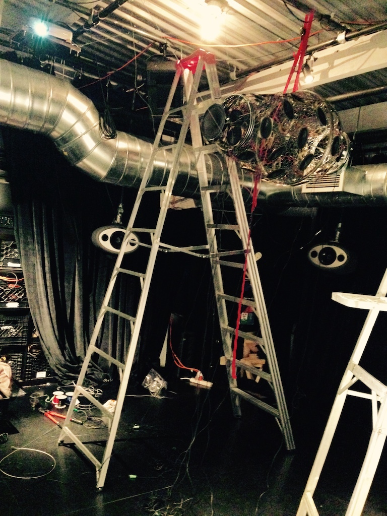
Hive 2.0 in ‘Stealth Mode’!
Issue 2 – cv.jit Reliability
In general, using cv.jit’s blob detection algorithms were VERY CPU intensive and not particularly reliable for tracking. Some tweaking could have been done to smooth things out, but there were still more issues with this approach!
Issue 3 – Height of Ceiling:
The Kinect would have been ceiling mounted and the center of the sculpture would have corresponded to the center of the camera frame. After taking into account the circumference of the sculpture, and given the field of view of the camera (i.e., how wide of an area the Kinect camera can capture), we could only capture an area of about two-three feet on each side of the sculpture. Not very exciting. We entertained using two Kinects and stitching the images together to expand the field of view. We also considered using three Kinects mounted on the wall to create an accurate capturing of the space, but between price ($400+), CPU performance, task complexity, and the other aforementioned problems, it was seeming like the Kinect wasn’t the tool for this project, and especially not in this space.
The Proximity Sensor Approach
Our solution was to find proximity sensors and mount them on each channel. This way, each speaker channel would be able to read how close ‘something’ was to it. As with many of our projects, we needed quite a few of these sensors to get the desired result, and of course costs grow exponentially depending on the amount of units needed.
There are two types of proximity sensors we tested. These were chosen because they fit into our constraints of accessibility, time, and budget.
Hive 2.0 Sensor Diagram
Infrared (IR) Proximity Sensors – We did not use these
IR proximity sensors would be like a simple version of the Kinect, in that the sensor shoots out an infrared beam and detects how far along something is in its path. The Kinect is essentially a 640 X 480 array of these units with longer ranges (as they are IR lasers). These simpler sensors cost about $10, so they could have been an affordable (six channels = $60) solution. The issue with the IR approach is that the accuracy of the readings varies depending on the density of the materials they interact with (i.e., cloth is more absorbent than a hard surface, thus reflecting the light differently, and thus influencing the consistency of the data coming in). Also, the data varies depending on ambient infrared light in the room, which could lead to inconsistent readings as more people enter, or as lighting conditions change. The sensors that were in the lower price range also did not have a long nor wide capturing range. Just like the Kinect, this wasn’t our solution.
Ultrasonic Proximity Sensors
Ultrasonic sensors work just like SONAR. The sensor emits a high frequency pulse and calculates the distance of an object/user by detecting the amount of time the sound takes to reflect back to the sensor.
Issues With Ultrasonic Sensors
There were still some issues with this approach in the case of Hive 2.0. One issue is that multiple ultrasonic sensors can interfere with each other, given that you have sound waves bouncing around in a space, and this can result in unstable data. Our solution was essentially to ‘strobe’ between the sensors so that only one was on at a time. In other words, if you have six sensors, turn all of the sensors inactive. Sensor 1 sends out and receives it’s pulse. Sensor 1 rests. Sensor 2 sends out and receives it’s pulse. Sensor 2 rests. Etc. Etc.
The issue with this approach is that you lower your time resolution. For example, if you have a sensor that reads data at 60 Hz (or think of it as 60 times per second), divide this by the amount of sensors (i.e., 60 Hz / 6 sensors) means that each sensor gets a ‘frame’ of data every 100 milliseconds (ms). You may not know it if you’re not used to computers, but that’s actually a lot of time lost, and this results in the user perceiving latency! For example, using video as an analogy, a 30p video is 30 frames per second, so you see an image every 33.33 milliseconds to create continuous motion. A ‘frame’ every 100 ms results in a frame rate of 10 frames per second! Not the best, and kind of choppy!
Another issue is that when getting close to the sculpture, there can be dead zones between the sensors, as they are mounted on the exterior of the sculpture. If you compare the Kinect floor tracking diagram to the Ultrasonic floor diagram, you’ll notice that the Kinect had no dead zones. However, despite these issues, ultrasonic sensors ended up being our most appropriate solution. Now let’s get into which ones we chose to use, and why.
What We Used
We tried two main brands of Ultrasonic sensors, both accessible at our local sensor go-to shop, Creatron. One was the Elec Freaks HC-SR04, which was a $9 option and would have cost about $60 for the project. The second was the MaxSonar LV EZ-0 which cost about $36 per unit ($216 for the project). After our tests, we concluded that the EZ-0 was worth the extra cash to get the best experience that we could achieve given our time/money limitations. But let’s go through a breakdown of why we made this choice:

EZ-0 VS HC-SR04!
HC-SR04
Summary:
Cost: $9
Working Voltage: DC 5V
Working Current: 15 mA
Reading Rate (approx): 16 – 17 Hz
Pins: 2 Digital, One Input, One PWM
Physical Dimensions (approx): 20 mm X 45 mm X 14 mm ( 13/16″ X 1 3/4″X 1 3/4″)
Range:
Officially: 2 cm – 4 m (3/4″ – 156″)
Our Test Results (approx): 2.5 cm – 1.21 m (1″ – 48′)
Beam Width (approx): 15°
We tested this HC-SR04 sensor in conjunction with the Arduino ping library. The sensor wasn’t bad, but had two major drawbacks. One was the sensor had a 15 degree beam, which was not as wide as the EZ-0’s beam, resulting in less of an area being tracked. Another issue is that the sensor ran at 40 Hz, which was half the rate of EZ-0, and would result in some nasty latency when six of these were racked up in our setup. In addition, the wiring also would have been slightly more complicated, as each sensor required the use of two digital pins – one to send the pulse, and one to receive it. 2 X 6 = 12 digital pins being used on our Arduino Uno! Yes we could have used a shift register or multiplexer, but we haven’t used those yet, and being very limited on time, we didn’t want to have any additional headaches with unknown variables. Additionally, this sensor was larger than the EZ-0, which made our mounting options for it potentially slightly more trick or labour intensive. The final blow was that the sensor’s reading distance was less than advertised, and only seemed to reliably read 3-4 feet, making it have little advantage over the Kinect approach. Now for the EZ-0.
MaxSonar LV – EZ-0
Summary:
Cost: $36
Working Voltage: 2.5-5.5V
Working Current: 2 mA
Reading Rate: 20 Hz
Physical Dimensions: 22 mm X 20 mm X 15 mm (7/8″ X 13/16″ X 9/16″)
Pins (for our use): 1 Analog Input
Range:
Official: 15.2 cm – 645 cm (6′ – 254″)
Our Test Results (approx): 76.2 cm – 3.048m (3″ – 120″) **Note we did not have the proper space to test the maximum advertised range, however we found it the most responsive within this range
Beam Width (Approx): 70°
Although it was about four times the cost per unit as the HC-SR04, we chose to use this sensor with Max 6 in conjunction with our custom rewrite of Lasse Vestergaard’s and Rasmus Lunding’s ArduinoInOutForDummies library. We had numerous reasons for choosing the LV EZ-0 over the HC-SR04. First off, it was slightly faster, and given that the specs of either sensor’s reading rate weren’t totally ideal to begin with (20 Hz = a reading every 300 ms), we needed as fast as we could afford. Also, the EZ-0 consumed less current (not a major concern in this scenario, but if we ever get the budget to add more sensors, this would really add up, although given the aforementioned reading rate, we would be reluctant to add any more of either of these models!). Using the analog readings from the sensors, it was both easier to set up, and required less Arduino pins (6 analog pins vs 12 digital pins). The sensor also had MUCH better documentation, including diagrams on how to use multiple sensors in conjunction without any shift registers or multiplexers! As a side note, we ended up using the ‘Sequential’ method versus the ‘Continuous Looping’ method, as the latter didn’t work as expected and appeared to operate no differently than the former. This may be something to do with how Max deals with the Arduino though.
From an aesthetic standpoint, this sensor was physically smaller, and easier to design mounts for. However, the main reason we chose the EZ-0 was that its range was significantly wider ( 70° vs 15° ) and longer (10 ft vs 4 ft) than the HC-SR04. Given that dead zones are an admitted design flaw with the Ultrasonic sensor approach, we needed a beam as wide as possible. Additionally, EZ-0 just seemed a bit more responsive and dynamic in general, so we opted to pay a bit more to give people the best experience we could provide.
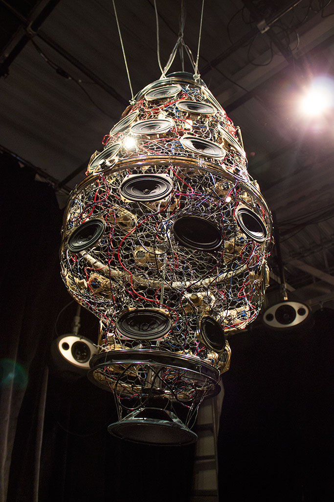
Hive 2.0 Sculpture
So there you have it! If any of you out there have any questions, we’d be happy to provide more insight into our process! Do you have any other tools to recommend to us, or have a better product(s) you’d like to sponsor us with? Contact us!

Have you looked if a variable frequency sensor/transmitter was available? using simple fourier transform it would allow you to do multiple sensor independant readings and also gives you information about the radial speed of objects measured(doppler radar). and because the measurement from multiple sensors is in the same time step it would also allow for angular position information(triangulation) and angular speed(change in angular position) to be known.
That’s an approach we never considered and very interesting approach indeed. By doing a quick Google, it looks like we may have to look into more expensive options if we want to do projects using a similar premise. There’s a nice little discussion here: http://electronics.stackexchange.com/questions/24835/multiple-ultrasonic-rangefinder-question about some of the limitations of using the multiple frequency approach. Definitely something we will research more.
Thanks so much for the suggestion!
Pingback: Video: Hive 2.0 is an interactive sound sculpture | Bits & Pieces from the Embedded Design World
Pingback: Hive 2.0 is an interactive sound sculpture | Atmel Bits & Pieces